A 2:1 stereo input multiplexer is included for selecting between line-level or microphone-level inputs. The mi-crophone input path includes a +32 dB gain stage and a low noise bias voltage supply. The PGA is available for line or microphone inputs and provides gain or atten-uation of 12 dB in 0.5 dB steps.
In the following network, run eBGP between Switch A and Switch B and iBGP between Switch B and Switch C so that Switch C can access the network 8.1.1.0/24 connected to Router A.
- ACX5048,ACX5096,SRX Series,vSRX. The Internet Protocol (IP) specifies a loopback network with the (IPv4) address 127.0.0.0/8. Most IP implementations support a loopback interface (lo0) to represent the loopback facility.
- Also, to re-create On-link, you simply use 0.0.0.0. Two more things. (1) When deleting routes, Windows deletes ALL routes on that Network Destination. So they need to be recreated as you noticed. (2) Sniffing on local loopback interface routes is not well supported in Windows, so you need to make sure loopback routes 'exits' the.
Network diagram for BGP basic configuration
Configure IP addresses for interfaces (omitted.)
Configure iBGP.
To prevent route flapping caused by port state changes, this example uses loopback interfaces to establish iBGP connections.
Because loopback interfaces are virtual interfaces, you need to use the
peer connect-interfacecommand to specify the loopback interface as the source interface for establishing BGP connections.Enable OSPF in AS 65009 to ensure that Switch B can communicate with Switch C through loopback interfaces.
# Configure Switch B
# Configure Switch C
The output information shows that Switch C has established an iBGP peer relationship with Switch B.
Configure eBGP.
The eBGP peers, Switch A and Switch B (usually belonging to different carriers), are located in different ASs. Their loopback interfaces are not reachable to each other, so directly connected interfaces are used for establishing BGP sessions.
To enable Switch C to access the network 8.1.1.0/24 that is connected directly to Switch A, add network 8.1.1.0/24 to the BGP routing table of Switch A.
# Configure Switch A.
# Configure Switch B.
# Show IP bgp peer information on Switch B.
Latest version of adobe reader free download for mac. Choco 1 4 2 – design photo collages. The output shows that Switch B has established an iBGP peer relationship with Switch C and an eBGP peer relationship with Switch A.
# Display the BGP routing table on Switch A.
# Display the BGP routing table on Switch B.
# Display the BGP routing table on Switch C.
NOTE: From the above outputs, you see that Switch A has not learned a route to AS 65009, and Switch C has learned network 8.1.1.0 but the next hop 3.1.1.2 is unreachable, so the route is invalid.
Redistribute connected routes.
Configure BGP to redistribute direct routes on Switch B, so that Switch A can obtain the route to 9.1.1.0/24 and Switch C can obtain the route to 3.1.1.0/24.
# Configure Switch B.
# Display the BGP routing table on Switch A.
Two routes 2.2.2.2/32 and 9.1.1.0/24 have been added in Switch A's routing table.
# Display the BGP routing table on Switch C.
Route 8.1.1.0 becomes valid with the next hop as Switch A.
Verification.
In the following figure, Switch B establishes eBGP connections with Switch A and C. Configure the No_Export community attribute on Switch A so that routes from AS 10 are not advertised by AS 20 to any other AS.
Network diagram for BGP community configuration
Configure IP addresses for interfaces (omitted.)
Configure eBGP.
# Configure Switch A.
# Configure Switch B.
# Configure Switch C.
# Display the BGP routing table on Switch B.
Switch B advertised routes to Switch C in AS 30.
# Display the routing table on Switch C.
Switch C learned route 9.1.1.0/24 from Switch B.
Configure the BGP community.
# Configure a routing policy.
# Apply the routing policy.
# Display the route on Switch B.
The route 9.1.1.0/24 is not available in the routing table of Switch C.

In the following figure, all switches run BGP.
There is an eBGP connection between Switch A and Switch B. There are iBGP connections between SwitchB and Switch C, and between Switch C and Switch D.
Switch C is a route reflector with clients Switch B and D.
Switch D can learn route 1.0.0.0/8 from Switch C.
Network diagram for BGP route reflector configuration
Configure IP addresses for interfaces (omitted.)
Configure BGP connections.
# Configure Switch A.
# Add network 1.0.0.0/8 to the BGP routing table.
# Configure Switch B.
# Configure Switch C.
# Configure Switch D.
Configure the route reflector.
# Configure Switch C.
Verify the above configuration.
# Display the BGP routing table on Switch B.
# Display the BGP routing table on Switch D.
Switch D learned route 1.0.0.0/8 from Switch C.
In the figure below, all switches run BGP. eBGP connections are between Switch A and Switch B, and between Switch A and Switch C. iBGP connections are between Switch B and Switch D, and between Switch C and Switch D.
OSPF is the IGP protocol in AS 200.
Configure the routing policies. Switch D should use the route 1.0.0.0/8 from Switch C as the optimal route.
Network diagram for BGP path selection configuration
| Device | Interface | IP address | Device | Interface | IP address |
|---|---|---|---|---|---|
| Switch A | Vlan101 | 1.0.0.0/8 | Switch D | Vlan400 | 195.1.1.1/24 |
| Vlan100 | 192.1.1.1/24 | Vlan300 | 194.1.1.1/24 | ||
| Vlan200 | 193.1.1.1/24 | Switch C | Vlan400 | 195.1.1.2/24 | |
| Switch B | Vlan100 | 192.1.1.2/24 | Vlan200 | 193.1.1.2/24 | |
| Vlan300 | 194.1.1.2/24 |
Configure IP addresses for interfaces (omitted.)
Configure OSPF on Switch B, C, and D.
# Configure Switch B.
# Configure Switch C.
# Configure Switch D.
Pixel film studios proteaser volume 4 download free. Configure BGP connections.
# Configure Switch A.
# Add network 1.0.0.0/8 to the BGP routing table on Switch A.
# Configure Switch B.
# Configure Switch C.
# Configure Switch D.
Configure attributes for route 1.0.0.0/8, making Switch D give priority to the route learned from Switch C.
# Configure a higher MED value for the route 1.0.0.0/8 advertised from Switch A to peer 192.1.1.2.
# Define a prefix-list to permit route 1.0.0.0/8.
# Define two routing policies, apply_med_50, which sets the MED for route 1.0.0.0/8 to 50, and apply_med_100, which sets the MED for route 1.0.0.0/8 to 100.
Huge casino slot wins. # Apply routing policy apply_med_50 to the route advertised to peer 193.1.1.2 (Switch C), and apply_med_100 to the route advertised to peer 192.1.1.2 (Switch B.)
# Display the BGP routing table on Switch D.
You can ensure that route 1.0.0.0/8 is the optimal route. Configure different local preferences on Switch B and C for route 1.0.0.0/ 8, making Switch D give priority to the route from Switch C.
# Define an ip prefix-list on Router C, permitting route 1.0.0.0/8.
# Configure a routing policy named localpref on Switch C, setting the local preference of route 1.0.0.0/8 to 200 (the default is 100.)
# Apply routing policy localpref to routes from peer 193.1.1.1.
# Display the routing table on Switch D.
You can see that route 1.0.0.0/8 from Switch D to Switch C is the optimal route.
In the following figure, all switches are BGP switches. There is a eBGP connection between Switch A and Switch B. Switch B and Switch C are connected over an iBGP connection. Enable GR for BGP so that the communication between Switch A and Switch C is not affected when an active/ standby main board switchover occurs on Switch B.
Network diagram for BGP GR configuration
Configure Switch A.
# Configure IP addresses for interfaces (omitted.)
# Configure the eBGP connection.
# Configure BGP GR stalepath-timeout (optional.)
# Add network 8.0.0.0/8 to the BGP routing table.
# Enable GR for BGP Peer.
Configure Switch B.
# Configure IP addresses for interfaces (omitted.)
# Configure the eBGP connection.
# Configure BGP GR restart-time and stalepath-timeout (Optional.)
# Configure the iBGP connection.
# Configure BGP to redistribute direct routes.
# Enable GR capability for BGP Peers.
# Configure BGP for non-stop forwarding
Configure Switch C.
# Configure IP addresses for interfaces (omitted.) http://cfbwxm.xtgem.com/Blog/__xtblog_entry/19222300-screenflick-2-7-42-cr2#xt_blog.
Design letters templates 1 6 download free. # Configure the iBGP connection.
# Configure BGP to redistribute direct routes.
BGP Configuration Example
# Enable GR for BGP Peer.
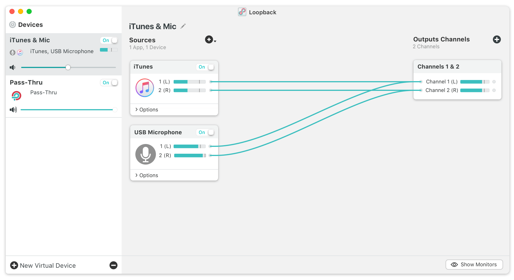
Loopback 1 2 – Route Audio Between Applications Pdf Format
After completing the above configuration, perform an active/standby switchover on Switch B. Switch A and Switch C should be able to ping each other without any packet drops. Also ensure that there are no flaps of BGP learned routes on the peer switches.